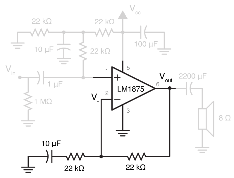
I needed to make a little speaker. The real reason? Because of a retro gaming session at work. However, there have been several times that I’ve needed a small cheap speaker that was suitable for delivering simple stimuli. I thought I would post a schematic and take this opportunity to give you an example of how Matlab can make impedance calculations easier, something I’ve talked a little about before.
The core of this amplifier is an LM1875 om-amp. The circuit shown above is a complete rip off of the schematic shown in Figure 2 of the data sheet, with a few unnecessary parts removed. Instead of trying to design a one from scratch, the point of this post will be to analyse the schematic given. After that, you’ll hopefully be able to make any changes.
Because we want to use a single sided power supply (i.e. our power supply gives us a positive rail and ground), we will need to “bias” the input to our amplifier, so when it receives no other input, it rests at half the supply voltage, giving the op-amp the ability to move negatively, and positively. We then place a capacitor in between the audio source (Vin) and the biased input, so that the bias voltage doesn’t leak back into the audio out. We also need some capacitors to stabilize our supply voltage, just in case the op amp needs to draw lots of current. All of this combines to be the input stage of our amplifier. We then want to amplify our input in a vaguely linear fashion, so we have negative feedback (where we can try to make sure the amplifier doesn’t waste current amplifying our bias voltage). Finally, on the output we have a large capacitor to make sure the speaker doesn’t see any of the bias voltage. The input stage is a bit of a pain to analyse, but I’ll be gentle.
Input Stage
All these capacitors and resistors will end up creating quite a filter, and we need to be aware of what properties it will have. To do a full analysis of this with pen and paper would be a real pain, but with Matlab, this will be quite quick.
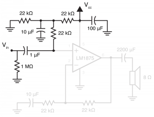 So the input stage is the parts of the circuit shown on the right. It looks complex to deal with because on top of all the capacitors, it also has a second voltage source. However, because at this point in the circuit we have solely linear elements, we can use a a technique called “superposition“. In this, what we do is analyse the circuit twice, once for each voltage source, and then add the results. In turn, we change all voltage sources to short circuits, apart from one. Thus, if we change Vcc to a short (to earth), not only does it get rid of the issue of the secondary voltage, but it also removes the 100 µF capacitor from the circuit (because it has an earth on both terminal).
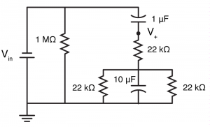 If we then redraw the input stage circuit, we can quickly see that the circuit wont be too difficult to solve. Let’s start with the two 22 kΩ resistors, and one 10 µF capacitor in parallel, these can be replaced with a single impedance
 . We know that the impedance of a capacitor is given by:
and for impedances in parallel, the equivalent impedance is:
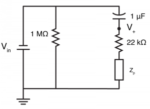
Thus we can calculate the impedance of the three elements in parallel as:
In matlab we can then calculate .
>> f = 0.1:0.1:100000; % Frequecy
>> w = f*2*pi; %Convert to angular frequency
>> zp = 1 ./ (2/22e3+j*w*100e-6);
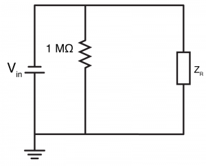 We can then calculate the impedance of the whole right hand side (
 ), by adding
to the 10 µF capacitor and 22 kΩ resistor that are in series with it.
>> zr = zp + 22e3 + 1./(j*w*10e-6);
At this point, we should look back at the simplified circuit of the input stage. We can see that the voltage is simply
minus the voltage lost over the 1 µF capacitor
. In order to calculate that, we need to know that current which passes through the
(
), which is simply found via Ohm’s law.
Factoring…
Finally, the transfer function is…
Which we can calculate and plot in Matlab.
>> input_transfer = 1 - 1 ./ zr * 1./(j*w*1e-6);
>> loglog(f, abs(input_transfer)); xlabel('Frequency (Hz)'); ylabel('|V(out)/V(in)|');
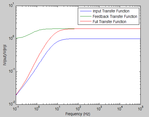
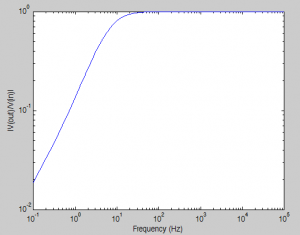 So, we have made a high pass filter, with a cut-off of about 10 Hz. But remember, we’re trying to do a full analysis here, and we’re using superposition, so now we have to turn
 into a short to ground, and repeat our analysis. But don’t freak out, this is going to be super simple. Why? Because we can treat
as being purely DC, and hence all of the capacitors will act as open circuits.
So if we convert all the capacitors to open circuits, we are left with a circuit with three resistors, one of which isn’t in the circuit because it is in series with a capacitor. Now the circuit has been simplified to a voltage divider with equal resistors. We know that means the input voltage () will be halved, and so in this case,
To complete the analysis, we add the two cases together, and so:
Feedback Stage
This wont be as bad as the above. We just need to remember that because we have negative feedback, the voltage at the inverting terminal of the op-amp will be the same as at the non-inverting terminal. We also need to use superpositioning again.
If we look from the perspective of , then
looks like the center of a voltage divider, between a resistor, and a resistor/capacitor. First, let’s calculate their impedance. The feedback resistor (
) has a simple impedance of 22 kΩ. The resistor/capacitor section (
) has a complex impedance. So in matlab:
>> rf = 22e3;
>> zg = 22e3 + 1./(j*w*10e-6);
The point of the voltage divider is, unsurprisingly to divide the voltage. Specifically, as gets larger relative to
then
has to get larger and larger to keep
equal to
(because more of the voltage is generated over
rather than
). With a normal resistive voltage divider, we could say
, here we can say:
However, as we know the value of , we can rearrange, and get:
So, given that we know is equal to
we can now say (for the superposition case where
is off):
So in Matlab, once we notice that most of that equation is the input_transfer variable we calculated earlier:
>> full_transfer = input_transfer .* (rf+zg) ./ zg;
Here it would be a good idea to think about what is actually going on. We did some filtering at the input stage, and then applied some amplification and filtering. We can view those all by plotting:
>> loglog(f, [abs(transfer); abs((rf+zg) ./ zg); abs(full_transfer)]); xlabel('Frequency (Hz)'); ylabel('|V(out)/V(in)|');
>> legend('Input Transfer Function', 'Feedback Transfer Function', 'Full Transfer Function')
So as you can see, most of the high pass filtering was achieved by the passive input filter, but because of the series capacitor to ground in the feedback path, low frequency signals were not amplified (because to DC signals, the ground half of the voltage divider provided infinite impedance).
Finally, we should address the other superposition case, where there is no input apart from . We know that in this case,
. Because of negative feedback, that means
. Using the equation we calculated earlier, we can then say:
However, here we need to stop and think. is purely DC. That means all the capacitors act as open circuits. That means
. Which means that the above equation is really:
We could have guessed this from looked at the graph above, and the feedback transfer function: it tends towards 1 for DC values.
Thus, the true, absolute final output equation is:
.
Output Stage
There is no point doing a full output analysis here, because the speaker is so cheap that it doesn’t have full specs. The only thing worth noting is that the huge capacitor on the output blocks the DC component of the output, i.e. . By being such a large capacitor, it presents almost no impedance to anything but the lowest of frequencies.
Build
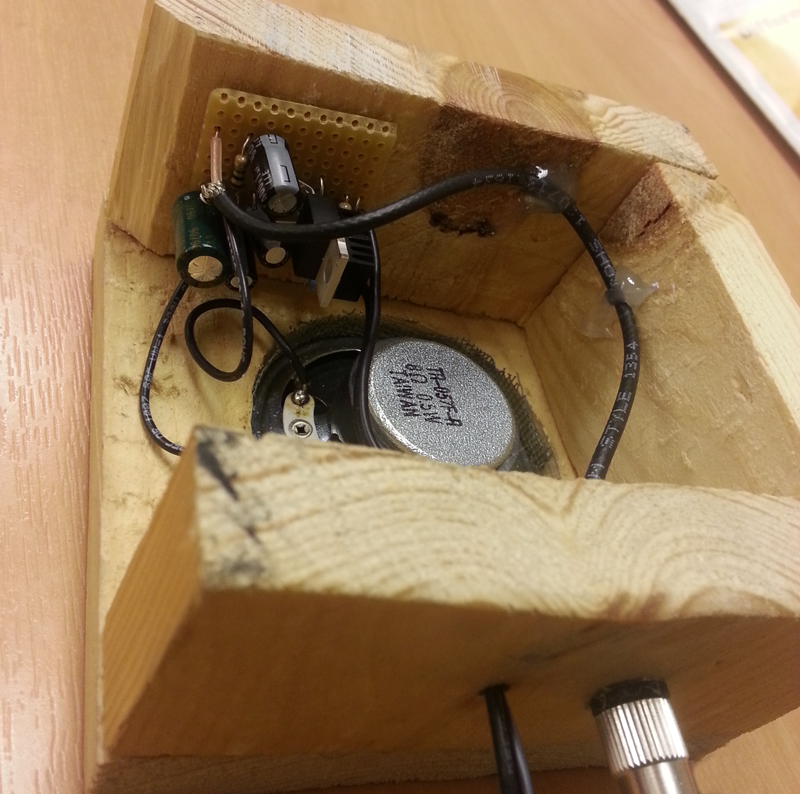
Pallet wood, a 2.25″ hole and some screws
| Description | Supplier | Part Number | Cost |
|---|---|---|---|
| LM1875 Op-amp | Farnell / Newark | 1468913 / 41K3523 | £2.05 / $3.08 |
| 8 Ohm speaker | Farnell / Newark | 4262323 / 19J5689 | £1 / $3.33 |
| 2200 uF, Electrolytic Capacitor | Farnell / Newark | 2282194 / 65R2740 | £0.245 / $0.198 |
| 10 x 100 uF, Electrolytic capacitors | Farnell / Newark | 1902882 / 55T0367 | £0.34 / $0.36 |
| 10 x 10 uF Electrolytic capacitor | Farnell / Newark | 1902913 / 55T0590 | £0.685 / $0.39 |
| 10 x 22k Resistors | Farnell / Newark | £0.1 / $0.1 | |
| 12 V DC supply | Farnell / Newark | 2424065 / 83T4338 | £5.41 / $10.04 |
| TOTAL | £9.83 / $17.50 |

